Building the Micro Mirror Free Software CDN
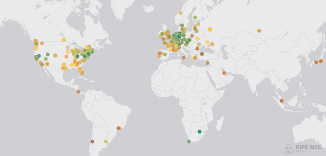
As should surprise no one, based on my past projects of running my own autonomous system , building my own Internet Exchange Point , and building a global anycast DNS service , I kind of enjoy building Internet infrastructure to make other people's experience online better. So that happened again, and like usual, this project got well out of hand. Linux updates You run apt update or dnf upgrade and your Linux system goes off and download updates from your distro and installs them. Most people think nothing of it, but serving all of those files to every Linux install in the world is a challenging problem, and it's made even harder because most Linux distributions are free and thus don't have a project budget to spin up a global CDN (Content Distribution Network) to have dozens or hundreds of servers dedicated to putting bits on the wire for clients over the Internet. How Linux distros get around this budget issue is that they host a single "golden" copy of all of