Arduino Four Digit Clock
After my last 7 segment clock, which only used one digit to progressively flash out the current time, the natural progression was to get a full 4 digit display and build a traditional digital clock.
Being back in the South Bay area meant Halted was within driving distance again, so I've taken several trips there to stock up for the next quarter stuck in Davis. I wasn't looking for anything specific, which is a DANGEROUS mindset to go in there with. You walk around, and you can pick up almost anything and convince yourself that you must be able to find something to do with this; whatever it is... Most of the trips are more Jeff bringing me along as his technical consultant, so it ends up being me wandering around drooling over the stuff I shouldn't buy for 10 minutes, answering his question about biasing photodiodes or something, and then back to drooling again.
Standing in the LED aisle, helping Jeff find 5mm green LEDs or some other specific part like that, when I saw it. An entire bin full of "2x2 digit 9 segment LED display," for the majestic price of NINETY-FIVE FREAKIN CENTS! That, good reader, is what we commonly refer to as less than a dollar. Needless to say, I bought that thing like fat kids buy candy.
Figuring Out the Pinout
Like most things at Halted, this screen came with little to no information. I didn't understand where they got "9 segment" from, since each digit looked to be 10 segments (7 numeral bars, decimal, and 2 for +/-), and with 15 pins on the board, the math didn't work out in any direction. This meant I just needed to start poking it with voltage, and see what happens.
Rule number one of LEDs: Limit the current. It'd be a real drag to get an awesome LED display, come home, and smoke one of the segments by pushing too much current through them. When you're working in a 5 volt environment, like the Arduino, a 330Ω resistor will give you 10mA through a red LED, and 15mA completely shorted out, neither of which stand a chance of doing damage. My test rig for the display was one wire attached to ground, and another attached to +5V through the 330Ω resistor.
Hold one of the wires on one of the pins, drag the other wire across the rest of the pins until something lights up. Mark down the pair of pins and which segment they light up on a piece of paper. Rinse, lather, and repeat.
Eventually, you end up with a drawing of the entire display, with a pair of numbers next to each segment, as to which two pins to use to light up that specific LED, which is useful later.
Results: In the end, it turned out to not be a 4 digit display, but a 3.5 digit display, which means that the top digit is only wired to be a 1. This is fine, because in 12 hour mode, a clock never gets above 12, so the top digit only ever needs to be 1 or blank. The display was also clearly meant to be installed in some piece of lab equipment. It has segments to make a plus or minus sign in front of the 1, and decimals after each digit. Might be useful if I ever want a 4 digit readout for +/-1999.
The pinout was pretty much everything I expected and hoped. All of each segment are connected to one pin (eg all of the middle bars share a pin, etc), and all of each digit share a pin. This means that to display a numeral on a digit, I enable the pin for the whole digit, and all of the pins for each individual segment. This has the problem that if you enable more than one digit at a time, you'll display the same digit on each. This is great if you're going for 666 or something, but less useful when you're displaying something like the time, and want it to work more than 10 times a day1.
So now we've got a three and a half digit display, but we can only display one digit at a time. What a drag, right? Luckily, microcontrollers are fast.
Like, really fast.
Like, so fast, you could light up one digit, then turn it off, light up three other digits in a row, then come back and light it up again, and some schmuck watching wouldn't be able to tell. This is called multiplexing, and is a fairly useful trick for when you have more LEDs to light up than you have pins to do it with. In this case, it means we can control 30 (6 + 8 + 8 + 8) LEDs with only 14 lines, instead of 31.
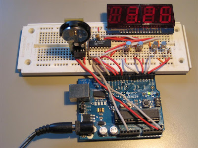
These four separate digit channels are controlled directly by four pins on the Arduino. Unfortunately, each segment needs to be run at 20mA, and with 8 segments per digit, this could mean 160mA at a time. This is much more than what each pin on an ATmega is rated for (40mA), so we need to use transistors to limit the load on the pins themselves. A simple way to do this is with a current limiting resistor, and an NPN transistor. The expected power dissipation in the transistor is pretty low, so I used a 2N2222, though you might be able to get away with even just a 2N3904.

Now that the positive end of the LEDs is taken care of, we need to be able to turn on or off each individual segment, to display actual numbers. This could be done with a set of current limiting resistors and 8 more Arduino pins, but I prefer to use an LED driver. This lets me use a simple 2-4 wire interface to tell the driver which LEDs to light up, and it handles all of the current limiting, while only using one resistor. This is nice because it means to change the current only requires changing one LED. I used an A6278 driver, which I found on Digikey. I used the chart in the datasheet to select a 1k resistor, since I wanted the output current to be 20mA per channel. Once I hooked the 8 cathodes for the 7 digit segments and the decimal to the driver, in software I wrote an eight bit map for each digit 0 - 9 based on the wiring.

The four transistor / resistor pairs can be seen in front of the display, with the control lines for each segment running off to the left to the 8 bit LED driver.
Now that we have 4 pins controlling which digit is lit up, and an LED driver running the individual segments based on manually calculated eight bit values for each digit, the software is simply a matter of extracting the current time from my old favorite DS1307 clock chip, pick one of the four digits, and display it for some period of time before moving on to display the next digit. The only extra thing I did was OR the lowest bit of the seconds into the decimal point on the hours digit, so the decimal between the hours and minutes flash to show that the clock is running.
Source code.
1. Ever hear the joke about the broken clock? It isn't broken, it's just right two times a day! Ba dum, tisshhh.

Being back in the South Bay area meant Halted was within driving distance again, so I've taken several trips there to stock up for the next quarter stuck in Davis. I wasn't looking for anything specific, which is a DANGEROUS mindset to go in there with. You walk around, and you can pick up almost anything and convince yourself that you must be able to find something to do with this; whatever it is... Most of the trips are more Jeff bringing me along as his technical consultant, so it ends up being me wandering around drooling over the stuff I shouldn't buy for 10 minutes, answering his question about biasing photodiodes or something, and then back to drooling again.
Standing in the LED aisle, helping Jeff find 5mm green LEDs or some other specific part like that, when I saw it. An entire bin full of "2x2 digit 9 segment LED display," for the majestic price of NINETY-FIVE FREAKIN CENTS! That, good reader, is what we commonly refer to as less than a dollar. Needless to say, I bought that thing like fat kids buy candy.
Figuring Out the Pinout
Like most things at Halted, this screen came with little to no information. I didn't understand where they got "9 segment" from, since each digit looked to be 10 segments (7 numeral bars, decimal, and 2 for +/-), and with 15 pins on the board, the math didn't work out in any direction. This meant I just needed to start poking it with voltage, and see what happens.
Rule number one of LEDs: Limit the current. It'd be a real drag to get an awesome LED display, come home, and smoke one of the segments by pushing too much current through them. When you're working in a 5 volt environment, like the Arduino, a 330Ω resistor will give you 10mA through a red LED, and 15mA completely shorted out, neither of which stand a chance of doing damage. My test rig for the display was one wire attached to ground, and another attached to +5V through the 330Ω resistor.
Hold one of the wires on one of the pins, drag the other wire across the rest of the pins until something lights up. Mark down the pair of pins and which segment they light up on a piece of paper. Rinse, lather, and repeat.
Eventually, you end up with a drawing of the entire display, with a pair of numbers next to each segment, as to which two pins to use to light up that specific LED, which is useful later.
Results: In the end, it turned out to not be a 4 digit display, but a 3.5 digit display, which means that the top digit is only wired to be a 1. This is fine, because in 12 hour mode, a clock never gets above 12, so the top digit only ever needs to be 1 or blank. The display was also clearly meant to be installed in some piece of lab equipment. It has segments to make a plus or minus sign in front of the 1, and decimals after each digit. Might be useful if I ever want a 4 digit readout for +/-1999.
The pinout was pretty much everything I expected and hoped. All of each segment are connected to one pin (eg all of the middle bars share a pin, etc), and all of each digit share a pin. This means that to display a numeral on a digit, I enable the pin for the whole digit, and all of the pins for each individual segment. This has the problem that if you enable more than one digit at a time, you'll display the same digit on each. This is great if you're going for 666 or something, but less useful when you're displaying something like the time, and want it to work more than 10 times a day1.
So now we've got a three and a half digit display, but we can only display one digit at a time. What a drag, right? Luckily, microcontrollers are fast.
Like, really fast.
Like, so fast, you could light up one digit, then turn it off, light up three other digits in a row, then come back and light it up again, and some schmuck watching wouldn't be able to tell. This is called multiplexing, and is a fairly useful trick for when you have more LEDs to light up than you have pins to do it with. In this case, it means we can control 30 (6 + 8 + 8 + 8) LEDs with only 14 lines, instead of 31.
These four separate digit channels are controlled directly by four pins on the Arduino. Unfortunately, each segment needs to be run at 20mA, and with 8 segments per digit, this could mean 160mA at a time. This is much more than what each pin on an ATmega is rated for (40mA), so we need to use transistors to limit the load on the pins themselves. A simple way to do this is with a current limiting resistor, and an NPN transistor. The expected power dissipation in the transistor is pretty low, so I used a 2N2222, though you might be able to get away with even just a 2N3904.


Now that we have 4 pins controlling which digit is lit up, and an LED driver running the individual segments based on manually calculated eight bit values for each digit, the software is simply a matter of extracting the current time from my old favorite DS1307 clock chip, pick one of the four digits, and display it for some period of time before moving on to display the next digit. The only extra thing I did was OR the lowest bit of the seconds into the decimal point on the hours digit, so the decimal between the hours and minutes flash to show that the clock is running.
Source code.
1. Ever hear the joke about the broken clock? It isn't broken, it's just right two times a day! Ba dum, tisshhh.