AVR Nixie Tube Thermometer
A few months ago I was wandering around the newstand in downtown Davis looking for something to read, when I found the January issue of Elektor, which had a feature article on building a nixie tube thermometer. It looked like an interesting project, and gave me enough pieces to roll my own using what I happen to have in my parts bins.
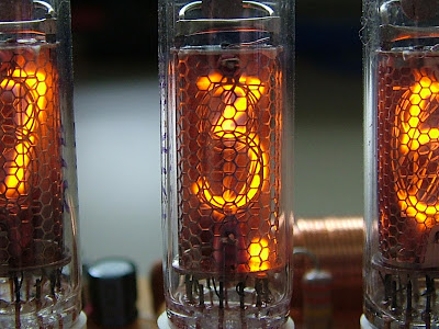 Nixie tubes were originally used in the 1950's and 1960's, before LED and LCD segmented displays were developed, to display numerical information from equipment such as volt meters and early computers. Nixie tubes operate by having 10 different shaped cathodes and an anode cage in a neon atmosphere. With a large positive voltage applied to the cage, and one of the cathodes grounded, electrons will be ejected from the cathode and ignite the neon immediately surrounding the specific cathode, which are formed in the shape of the digits 0-9.

Nixie tubes went out of use quickly once it was possible to replace them with LEDs and LCDs, due to their requirement for high voltage, their fragility, and relatively high power requirement. The steampunk movement has brought back their use as a novelty, which has unfortunately driven up the cost of larger tubes on the second market (Obviously, production of nixie tubes halted decades ago). The IN-16 tubes used for my thermometer are about as big as you can get them while still being affordable, being about $3 a piece on eBay.

Video:
The circuit is composed of two major parts: The digital control on the front of the circuit board, and the high voltage power supply behind the tubes.
 The digital control is driven by an ATTiny2313 AVR, which reads the current temperature from a DS1631 temperature sensor, optionally converts the Celsius reading into Fahrenheit, and then decodes it into three digits of BCD, output to the nixie driver chips, which decode the BCD to 1-of-10 while being able to handle the high voltages from the nixie tubes.
The jumper next to the AVR controls whether the temperature is displayed in Celsius or Fehrenheit.
The Nixie tubes have a junction voltage of about 120V, meaning the current through the display is determined by the remainder of the voltage across the current limiting resistors: (180V-120V) / 22k = 2.7mA.
Parts list for control circuitry:

 The power supply was where the magazine article was most valuable. The MC34063 is a Texas Instruments boost convert, which means it uses an inductor to step low-voltage high-current to high-voltage low-current. I have done this open loop before, where the on and off times of the grounding switch on the right of the inductor are fixed and you just hope it happens to be the right voltage. The MC34063 on the other hand is able to run this circuit closed loop, meaning it samples the output of the circuit and uses that to adjust how it controls the boost circuitry to maintain a fixed voltage, regardless of load. This is done by the voltage divider, which divides the desired voltage down to 1.25V to be compared with the voltage reference inside the chip.
The 330pF capacitor controls the speed the boost converter runs at, and is mostly a function of how big the power inductor and voltage ratio are. I just used a value close to that in the schematic, but ideally you would calculate this using the tables from the datasheet.
Not shown in the schematic is the very standard 7805 linear regulator used to step the 12V down to the 5V required for all of the digital control.
Parts list for power supply:


Nixie tubes went out of use quickly once it was possible to replace them with LEDs and LCDs, due to their requirement for high voltage, their fragility, and relatively high power requirement. The steampunk movement has brought back their use as a novelty, which has unfortunately driven up the cost of larger tubes on the second market (Obviously, production of nixie tubes halted decades ago). The IN-16 tubes used for my thermometer are about as big as you can get them while still being affordable, being about $3 a piece on eBay.

Video:
The circuit is composed of two major parts: The digital control on the front of the circuit board, and the high voltage power supply behind the tubes.

The jumper next to the AVR controls whether the temperature is displayed in Celsius or Fehrenheit.
The Nixie tubes have a junction voltage of about 120V, meaning the current through the display is determined by the remainder of the voltage across the current limiting resistors: (180V-120V) / 22k = 2.7mA.
Parts list for control circuitry:
- 1x ATTiny2313 AVR
- 1x DS1631
- 3x IN-16 Nixie tubes
- 3x K155 or 74141 Nixie decoder
- 3x 22kΩ resistor
- 3x 4.7kΩ resistor
- 1x MPSA42 300V NPN signal transistor (Digikey)


The 330pF capacitor controls the speed the boost converter runs at, and is mostly a function of how big the power inductor and voltage ratio are. I just used a value close to that in the schematic, but ideally you would calculate this using the tables from the datasheet.
Not shown in the schematic is the very standard 7805 linear regulator used to step the 12V down to the 5V required for all of the digital control.
Parts list for power supply:
- 1x MC34063 boost converter (I managed to smoke the first one with 180V pretty quickly, so having it in a socket and having spares is a good idea) (Digikey)
- 1x 7805 5V linear regulator
- 1x IRF820 MOSFET
- 1x 500μH power inductor (Digikey)
- 1x 1N4937 600V fast-recovery diode
- 2x 100μF 100V capacitors (or a single cap rated for >200V)
- 1x 820k resistor
- 1x 5.6k resistor
- 1x 150Ω resistor
- 2x 47μF capacitor (25V)
- >2x 0.1μF capacitors (25V) - Apply liberally throughout the circuit